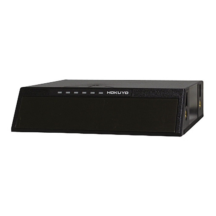
UCT-10LCM

Only 20 mm thick, this ultra-slim 3D LiDAR offers up to 10 m detection with a wide 100° (H) × 6° (V) scan,
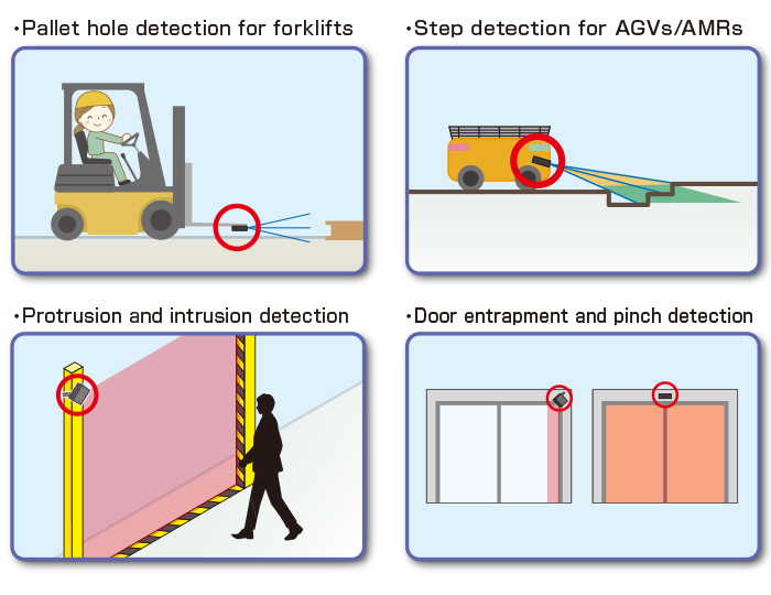
It is ideal for forklift pallet hole detection, AGV/AMR step detection, and safety applications such as intrusion and door pinch detection.
Overview
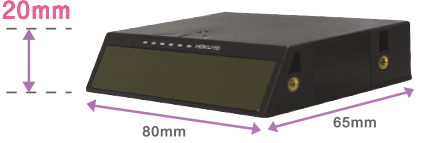
Compact size
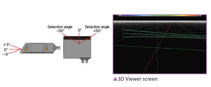
Multi-layer 3D scanning
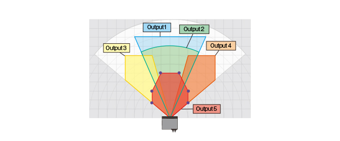
Flexible area configuration
Multi-echo function
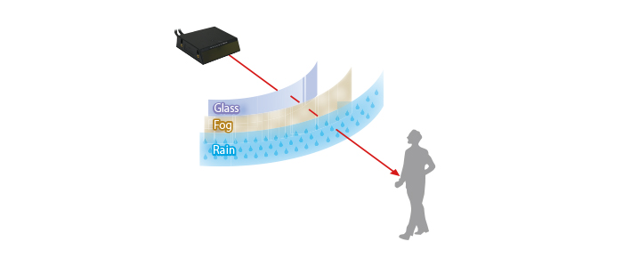
Multi-echo(LX mode):
You can receive multiple echoes such as rain or fog in one direction and select the distance data from each.
Filter function(LA mode):
If there is no continuous object in the same place (STEP) with the rain filter, it will be removed.
Self-diagnostic function
Applications
Model
| Model No. | Part No. |
| UCT-10LCM | UUCT002 |
Specification
| Model | UCT-10LCM |
|---|---|
| Supply Voltage | DC12V / DC24V (operation range: 10 to 30V, ripple within 10%) |
| Power Consumption | 3W |
| Light Source | Laser semiconductor (905nm) |
| Laser Safety | Class 1 (IEC60825-1:2014) Class 1 Laser Product |
| Accuracy *1 | ±40 mm |
| Repeated Accuracy *1 | σ < 20 mm |
| Detection Range and Object *1 |
■ Scan angle range: -45° to +45° 0.05 m to 10 m (reflectivity 90%, white kent sheet 600 × 2000 mm) 0.05 m to 4 m (reflectivity 10%, black paper 600 × 2000 mm) ■ Scan angle range: -50° to -45° and +45° to +50° 0.05 m to 8 m (reflectivity 90%, white kent sheet 600 × 2000 mm) 0.05 m to 3 m (reflectivity 10%, black paper 600 × 2000 mm) Maximum measurement distance: 30 m Minimum detectable size: 35 mm (at 4 m), 90 mm (at 10 m) |
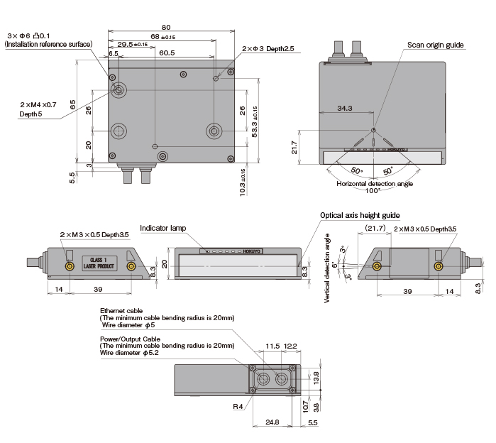
| Scan Angle | 100° |
| Vertical Angles |
Layer 1: 0° Layer 2: +3° Layer 3: -3° * Vertical angle in the front step |
| Scan Speed |
Multi-layer mode: 16.7 ms (motor speed: 2400 rpm / 3 layers) Single-layer mode: 50 ms |
| Measurement Resolution | 1 mm |
| Angular Resolution | 0.125° |
| Startup Time | Within 10 seconds (may exceed under specific startup conditions) |
| Outputs |
Total 7 outputs (NPN open collector output, DC 30V, 100 mA MAX, residual voltage < 2 V) Output 1–5: OFF when detection occurs in the corresponding area Output 6: ON during normal operation, OFF during malfunction Output 7: Reference output (ON during normal operation) Note: Outputs 1 to 5 and Output 7 are switched OFF during a malfunction state. |
| Inputs |
Total 1 input (photo-coupler input) Input 1: For switching the detection area |
| Output Response Time |
Multi-layer mode: 37 ms *2 Single-layer mode: 70 ms Note: Additional ON/OFF delay settings are possible (LA mode only). |
| Area Switching Time |
Multi-layer mode: 24 ms Single-layer mode: 57 ms |
| Interface | Ethernet 100BASE-TX |
| LED Display |
Power indicator (blue): Lights during normal operation; blinks during startup, configuration,
reference output operation, and malfunction states. Output indicators 1 to 5 (orange): Light up when detection occurs in the area (off during LX mode). Blink patterns indicate malfunction status. |
| Connection | Power and I/O: Connector (1 m), Ethernet: RJ45 (1 m) |
| Ambient Operating Temperature | -10 to +50 °C, below 85% RH (without dew or frost) |
| Storage Temperature | -30 to +70 °C, below 85% RH (without dew or frost) |
| Ambient Light *3 | Less than 100,000 lx (indirect light) |
| Vibration Resistance |
10–55 Hz, double amplitude 1.5 mm, 2 hours each in X, Y, Z directions 55–200 Hz, 98 m/s² (10 G), 2-minute sweep, 1 hour each in X, Y, Z directions |
| Shock Resistance | 196 m/s² (20 G), X, Y, Z directions, 10 times each |
| Electromagnetic Compatibility (EMC) |
EN 55011:2016+A1:2017+A2:2021 EN IEC 61000-6-4:2019 EN IEC 61000-6-2:2019 |
| Protective Structure | IP65 |
| Weight | 100 g (excluding cable) |
| Material |
Optical window: Acrylic Bottom case: Aluminum Top cover: Polycarbonate |
| Dimensions (W × D × H) | 80 mm × 65 mm × 20 mm |
| IMU *4 |
3-axis acceleration and 3-axis angular (TDK InvenSense: IIM-42652) Relative position to measurement origin: X: 17.1 mm, Y: 8.2 mm, Z: -8.3 mm |
| Communication Protocol *5 | SCIP (TCP/UDP), VSSP (TCP) |
*1: Under factory standard testing conditions using a white kent sheet.
*2: The slowest response time applies when continuous detection is possible in multi-layer mode.
If continuous detection is not possible, the response time is the same as in single-layer mode.
*3: Detection is not guaranteed under direct sunlight or strong ambient light.
Ensure that no direct sunlight enters the sensor.
*4: For details, refer to the data sheet.
*5: For details, refer to the respective communication specifications (C-42-04609, C-42-04610).
External dimension
I/O Circuit
I/O Circuit Connection Example
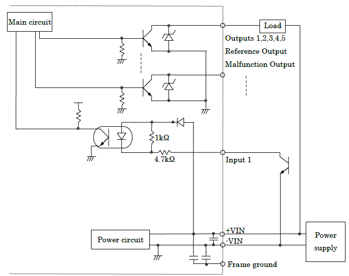
Please ensure it is grounded to the housing.
Power & I/O Cable
Cable length: 1000 mm
Conductor size: 28 AWG
Conductor insulation outer diameter: approx. 0.58 mm
Overall cable diameter: approx. Ø5.2 mm
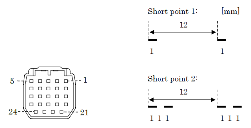
| Pin No. | Wire Color | Signal Name |
| 1 | Orange (Red mark 1) | +VIN (12VDC / 24VDC) |
| 2 | Orange (Black mark 1) | -VIN |
| 3 | Gray (Red mark 1) | Output 1 |
| 4 | Gray (Black mark 1) | Output 2 |
| 5 | White (Red mark 1) | Output 3 |
| 6 | White (Black mark 1) | Output 4 |
| 7 | Yellow (Red mark 1) | Output 5 |
| 8 | Yellow (Black mark 1) | NC |
| 9 | Pink (Red mark 1) | NC |
| 10 | Pink (Black mark 1) | Input 1 |
| 15 | White (Red mark 2) | Reference Output |
| 16 | White (Black mark 2) | Fault Output |
*Leave unused input/output wires open.
Ethernet Cable
Cable length: 1000 mm
| Wire Color | Signal Name |
| White (Orange) | TX+ |
| Orange | TX- |
| White (Green) | RX+ |
| Green | RX- |
Downloads
Before Download
If you have not registered as a member, please register as a member by clicking the "Registration".
If you are already a member, please agree to the following terms and click the "Agree".
License for Downloading Materials
When downloading the product specifications, drawings and various types of materials and software related to the Hokuyo's product line, please read the terms of use in advance and then utilize the same with your understanding and consent. In case of dissent, please understand that you cannot register to and be recognized in the download page. (And the Terms of Use may be revised without prior notice.)
Terms of Use
- Intellectual Property Rights
-
- Copyrights and the other rights to contents such as sentences, data and software published on this Website (hereinafter referred to as "Contents") are held by Hokuyo or its suppliers.
- The secondary application (copy, diversion, defacement, analysis, transmission, assignment, rental, licensing, and usage for the purpose of business activities or commercial gain) of the Contents on this Website posted by Hokuyo is strictly prohibited without our prior approval. Specific terms of use described for each download site or Contents shall apply in preference to the Terms of Use.
- Provision of the Contents on this Website by Hokuyo means neither a transfer of the patent rights, design rights, and/or the other intellectual property rights to inventions and designs in the Contents, nor a grant of any rights based on the intellectual property rights.
- Disclaimer
-
Hokuyo pays full attention to the information that appears on this Website, but does not take responsibility for the following items:
- The information that appears on this Website is always the latest version, and is updated or corrected timely and properly;
- The information that appears on this Website is accurate, useful and safe;
- Customer's damage incurred by the use of this Website, including changes or deletions of the information, discontinuation or suspension of the publication; and
- Any and all damage incurred by using this Website.
Download List
| Category | File name | File size | Date modified | Download |
|---|---|---|---|---|
|
|
Specification_UCT-10LCM
|
---
|
2026-01-26
|
|
|
|
Users Manual_UCT-10LCM
|
---
|
2026-01-26
|
|
|
|
SCIP Protocol Specification_UCT-10LCM
|
---
|
2026-01-26
|
|
|
|
VSSP Protocol Specification_UCT-10LCM
|
---
|
2026-01-26
|
|
|
|
AreaDesigner_Prime_1.0.0 (rev.2850)_installer
|
---
|
2026-01-26
|
|
|
|
Waveform Viewer Application Ver. 2.1.0
|
---
|
2026-01-26
|
|
|
|
Data Viewing Tool_UrgBenriPlus_2.3.2(rev.343)
|
---
|
2024-07-22
|
|
|
|
IP_Discovery_2.3.0(rev.96) IP address changing tool
|
---
|
2025-09-11
|
|
|
|
2DCAD(DXF)_UCT-10LCM
|
---
|
2026-01-26
|
|
|
|
3DCAD(IGES/STEP/Parasolid)_UCT-10LCM
|
---
|
2026-01-26
|
Relation Products

- Scanning Rangefinder
- Photoelectric Switch
- Sensor for Iron & Steel Industry
- Optical Data Transmission Device