The explanation of parallel type operation
Explanation of connections
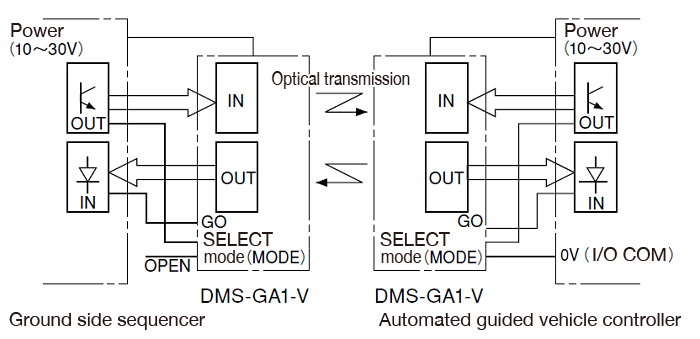
As an example, explain the case where DMS-GA1-V (4BIT data transmission) is used for data transmission between an automatic guided vehicle and the ground.
Connect the input terminal, output terminal, GO terminal, and SELECT terminal of the optical data transmission device to the input / output terminals of the microcomputer on both the ground side and automatic guided vehicle side.
Also, connect the MODE terminal to 0V on the automatic guided vehicle side, set the MODE terminal on the ground side to OPEN, set the ground side to a transmit standby mode, and set the automatic guided vehicle side to a receive standby mode.
Description of operation sequence
After the automatic guided vehicle enters the transmission / reception area of the optical data transmission device and stops, set the SELECT terminal on the automatic guided vehicle side to HIGH and wait for the GO terminal to turn LOW.
After confirming that the GO terminal is LOW, data is exchanged. After completion, lower the SELECT terminal of the automatic guided vehicle to LOW and start.
The transmission time in this case is the signal transmission time (100ms) + sequence control time.
If the SELECT terminal is used with OPEN, it may interfere with other photoelectric sensors.
Even if the signal of the photoelectric sensor enters the optical data transmission device, an erroneous output will not occur, but there is a possibility that an erroneous output will be output to the photoelectric sensor side.
The ground side set to the transmission standby mode is constantly emitting signals, so be careful when arranging it.
There is no problem on the reception standby mode (automated guided vehicle) side because there is no signal until it receives the signal.
- Scanning Rangefinder
- Photoelectric Switch
- Sensor for Iron & Steel Industry
- Optical Data Transmission Device