How to Use
FEATURE DETAIL
How to UseOptical Data Transmission Device
Optical axis adjustment method for serial type
About the optical axis adjustment
We will introduce the optical axis adjustment method using the BWF-11A/11B type as an example. Please note the following before making any adjustments.
(1) The reliable data transmission cannot be performed while adjusting the optical axis. During that time, lock the device connected with the transmission device so that it will not operate.
(2) Adjust the optical axis at the maximum distance used. After completion, check the level indicator light as moving closer to the trolley side.
(3) Adjust the optical axis in the pairs on the ground side and the trolley side (Using a transceiver, etc.is recommended)
(4) Do not move BWF-11A / 11B at the same time when adjusting the optical axis.
[Step 1] Preparation for adjustment
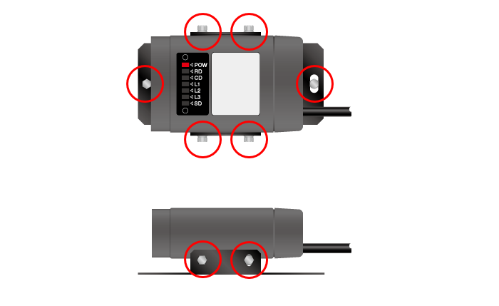
Loosen the screws on the top and bottom (4 screws) and left and right (2 screws) of each other.
Visually align to face each other straightly and fix them temporarily so that they do not move.
[Step 2] Loosen the screw on BWF-11A
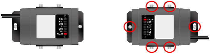
Since it will be adjusted one by one, firstly loosen the top, bottom, left and right screws of BWF-11A a little.
[Step 3] Check the level indicator
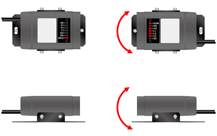
Move BWF-11A up / down / left / right and adjust so that the light receiving indicator of BWF-11B lights up in sequence with CD, L1, L2, and L3.
(At this time, the worker on the BWF-11B side informs the worker on the BWF-11A side of the state of the indicator light with a transceiver.)
[Step 4] Adjustment of BWF-11B
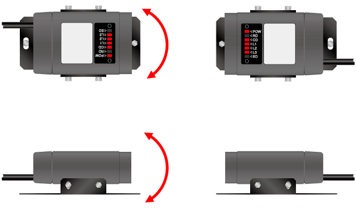
Next, adjust the BWF-11B side. [Procedure 2] [Procedure 3] Adjust in the same way.
Product's Category
- Scanning Rangefinder
- Photoelectric Switch
- Sensor for Iron & Steel Industry
- Optical Data Transmission Device