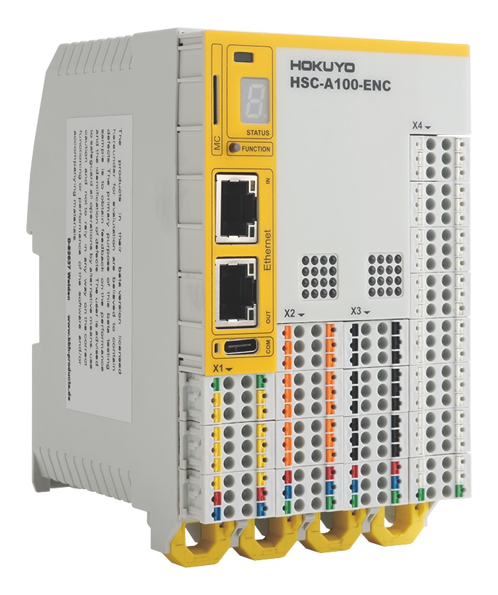
HSC-A100-ENC
Safety controller with 16 inputs and 8 outputs
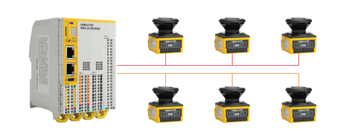
Up to 6 UAM safety laser scanners can be connected via serial communication
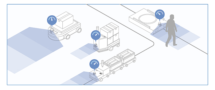
Speed monitoring is also possible with the encoder input.
It is used to control the safety-related parts of AGVs and industrial robots.
Overview
Product introduction
From detection to control with scanner + controller
HSC controls the AGV such as stopping or slowing down based on input signals from UAM.
PL
PLe is the highest safety level, which is higher than the AGV safety standards.
Reduced wiring

This makes wiring much easier than connecting to other devices and also eliminates the risk of incorrect wiring.
Maximum number of connections

On the other hand, by using HSC as master and UAM series as slave, HSC can have 2 master systems and it allows up to 6 slave UAM units to be connected.
Speed Monitoring

You can set up speed monitoring by selecting "Device Scheme" in the configuration software.
Safety standard JIS D6802
*Please refer to Japanese Industrial Standards JIS D6802 for the details.
System structure
It is necessary for safety controller to receive information from the encoder (position detection sensor) used for motor control.
Application
Collaborative robot: safety control of surroundings
Crane: Speed control and operating range control
Specification
| Item | Specification | |||
| General Data | Max. no. of expansion modules | 2×RJ-45 (Ethernet) | ||
| Interface of expansion modules | 16 | |||
| Number of safe digital inputs | PNP-switching | 6+2* +4 | PNP/NPN can be set in HSC Project designer |
|
| NPN-switching | 2 | |||
| Number of relay outputs | 2 | |||
| Number of analog inputs | 2 | |||
| Number of scanner connections (data interface) | 6 | |||
| Number of encoder interface | 4 (8x6pins) | |||
| Type of connection | Plug-in terminals with spring connection | |||
| Electrical Data | Supply voltage | 24VDC;2A(-37.5%,+30%) | ||
| Fuse | 24+ | Min. 32VDC;Max. 2A | ||
| AQ1+ | Min. 32VDC;Max. 10A | |||
| Max. power consumption (logic) | 4.7W | |||
| Rated data digital inputs | 24VDC; 20mA Typ2 (IEC61131-2) | |||
| Rated data digital outputs | 24VDC; 0.5A | |||
| Rated data digital outputs | PNP-switching | 24VDC;2A | ||
| NPN-switching | 24VDC;2A | |||
| Pulse outputs | 24VDC;250mA | |||
| Rated data relay outputs | 240VAC;24VDC;2A | |||
| Rated data analog inputs | -10..+10V,4..20mA | |||
| Environmental Data | Temperature (operation) | -25℃…+55℃ | ||
| Temperature (storage and transport) | -25℃…+70℃ | |||
| Class of protection | IP20 Connectors IP00 (EN60529) |
|||
| Climatic category | 3K24 (DIN EN60721-3-3) | |||
| Pollution class | 2(EN60664-1) | |||
| EMC | DIN EN6 1800-3, DIN EN6 1800-5-1 DIN EN62061, DIN EN62477-1 DIN EN55011 |
|||
| Shock | 15 G/11ms.10G/16ms and 5G/11ms in all three axes |
|||
| Vibration / shock-resistance | Conforms to EN60068-2-6/EN60068-2-27 IEC60068-2-64 |
|||
| Max. appl. height | ≦2000m | |||
| Mechanical Data | Dimension (HXDXW) | 124mm×95mm×76mm | ||
| Weight | 413g | |||
| Mounting | to snap on top-hat rail | |||
| Min. terminal cross-section/AWG | 0.2㎟/24 | |||
| Max. terminal cross-section/AWG | 1.5㎟/16 | |||
External dimension
I/O Circuit
PIN assignment
① Data interface, Voltage supply
| X1 | |||
| PIN | 1-PE | 2-PE | Protection earth |
| 3-RS-485_1+ | 4-RS-485_1- | Serial interface 1 | |
| 5-RS-485_1+ | 6-RS-485_1- | ||
| 7-RS-485_1+ | 8-RS-485_1- | ||
| 9-RS-485_2+ | 10-RS-485_2- | Serial interface 2 | |
| 11-RS-485_2+ | 12-RS-485_2- | ||
| 13-RS-485_2+ | 14-RS-485_2- | ||
| 15-VCC_N | 16-VCC_OU | Voltage supply+24V※1 | |
| 17-GND | 18-GND | Voltage GND※1 | |
Connect Pin 15(17) to external power supply. It is possible to supply the power to the scanner from pin 16(18).
② I/O interface, Voltage supply
| X2 | |||
| PIN | 1-NC | 2-NC | Safe digital inputs |
| 3-I0.0 | 4-I0.8 | ||
| 5-I0.0 | 6-I0.9 | ||
| 7-I0.2 | 8-I0.10 | ||
| 9-I0.3 | 10-I0.11 | ||
| 11-I0.4 | 12-I0.12 | ||
| 13-I0.5 | 14-I0.13 | ||
| 15-I0.6 | 16-I0.14 | ||
| 17-I0.7 | 18-I0.15 | ||
| 19-VCC_N | 20-VCC_IN | Voltage supply+24VDC※2 | |
| 21-GND | 22-GND | 0VDC※2 | |
| 23-PE | 24-PE | ||
③ I/O interface, Voltage supply
| X3 | ||||
| PIN | 1-Q0.0 | Safe digital outputs | 2-P1/Q0.6 | Non-safe pulse output / Safe digital output |
| 3-Q0.1 | 4-P2/Q0.7 | Non-safe pulse output / Safe digital output | ||
| 5-Q0.2 | 6-Q0.8_PP/Q0.8_P | Safe output PNP/NPN switching 00 | ||
| 7-Q0.3 | 8-Q0.9_PP/Q0.9_N | Safe output PNP/NPN switching 01 | ||
| 9-Q0.4 | 10-Q0.10 _PP/Q0.10_P | Safe output PNP/NPN switching 02 | ||
| 11-Q0.5 | 12-Q0.11_PP/Q0.11_N | Safe output PNP/NPN switching 03 | ||
| 13-Q0.12 _R1.1 | Relay output 1 | 14-Q0.12_R1.2 | Relay output 1 | |
| 15-NC | No function | 16-NC | No function | |
| 17Q0.14_R2.1 | Relay output 2 | 18-Q0.14_R2.2 | Relay output 2 | |
| 19-VCC_IN | I/O +24VDC ※ 3 | 20-VCC_IN | I/O+24VDC ※ 3 | |
| 21-GND | I/O 0VDC ※ 3 | 22-GND | I/O 0VDC ※ 3 | |
| 23-PE | Protective earth | 24-PE | Protective earth | |
④ Encoder interfaces
| X4 | ||||
| Encoder 1 | PIN | 1-ENC1_ Data+INCA+ | 2-ENC1_Data-lNCA- | TTL/HTL,SinCos. Resolver |
| 3-ENC1_ CLK+ INCB+ | 4+ENC1_ CLK-INCB- | |||
| 5-ENC1_Z+ | 6-ENCl_Z- | |||
| 7-EUT1 _U_Out+ | 8-ENC1_U_Out- | |||
| 9-ENC1_U_IN+ | 10-ENC1_U_ln+ | |||
| 11-NC | 12-NC | |||
| Encoder 2 | PIN | 13-ENC2_Data+ | 14 -ENC2_Data- | TTL/HTL,SinCos, Resolver, Analog |
| 15-ENC2_CLK+ | 16-ENC2_CLK- | |||
| 17-ENC_Z+ | 18-ENC2_Z- | |||
| 19-EUT2_U_Out+ | 20-ENC2_U_Out- | |||
| 21- ENC2_U_ln+ | 22-ENC2_U_ln- | |||
| 23-Analog_lN1+ | 24-Analog_lN1- | |||
| Encoder 3 | PIN | 25-Analog_lN2+ | 26-Analog_IN2 | TTL/HTL,SSI, Analog |
| 27-ENC3_Data+ | 28-END3_Data- | |||
| 29-ENC3_CLK+ | 30-ENC3_CLK- | |||
| 31-ENC3_Z+ | 32-ENC3_Z- | |||
| 33-EUT3_U_Out+ | 34-ENC3_U_Out- | |||
| 35-ENC3_U_IN+ | 36-ENC3_U_ln- | |||
| Encoder 4 | PIN | 37-ENC4_Data+ | 38-ENC4 _Data- | SSI |
| 39-ENC4_CLK+ | 40-ENC4_CLK- | |||
| 41-ENC4_Z+ | 42-ENC4_Z- | |||
| 43-EUT4_U_Out+ | 44-ENC4_U_Out- | |||
| 45-ENC4_U_ln+ | 46-ENC4_U_ln- | |||
| 47-PE | 48-PE | |||
⑤ Fieldbus interfaces
| EtherCAT interface(RJ45) | |||
| PIN | Name | Description | Color |
| 1 | TX+ | Transmit Data+ | white-orange |
| 2 | TX- | Transmit Data - | orange |
| 3 | RX+ | Receive Data+ | white-green |
| 4 | NC | Not used | blue |
| 5 | NC | Not used | white-blue |
| 6 | RX- | Receive Data - | green |
| 7 | NC | Not used | white-brown |
| 8 | NC | Not used | brown |
Downloads
Before Download
If you have not registered as a member, please register as a member by clicking the "Registration".
If you are already a member, please agree to the following terms and click the "Agree".
License for Downloading Materials
When downloading the product specifications, drawings and various types of materials and software related to the Hokuyo's product line, please read the terms of use in advance and then utilize the same with your understanding and consent. In case of dissent, please understand that you cannot register to and be recognized in the download page. (And the Terms of Use may be revised without prior notice.)
Terms of Use
- Intellectual Property Rights
-
- Copyrights and the other rights to contents such as sentences, data and software published on this Website (hereinafter referred to as "Contents") are held by Hokuyo or its suppliers.
- The secondary application (copy, diversion, defacement, analysis, transmission, assignment, rental, licensing, and usage for the purpose of business activities or commercial gain) of the Contents on this Website posted by Hokuyo is strictly prohibited without our prior approval. Specific terms of use described for each download site or Contents shall apply in preference to the Terms of Use.
- Provision of the Contents on this Website by Hokuyo means neither a transfer of the patent rights, design rights, and/or the other intellectual property rights to inventions and designs in the Contents, nor a grant of any rights based on the intellectual property rights.
- Disclaimer
-
Hokuyo pays full attention to the information that appears on this Website, but does not take responsibility for the following items:
- The information that appears on this Website is always the latest version, and is updated or corrected timely and properly;
- The information that appears on this Website is accurate, useful and safe;
- Customer's damage incurred by the use of this Website, including changes or deletions of the information, discontinuation or suspension of the publication; and
- Any and all damage incurred by using this Website.
Download List
| Category | File name | File size | Date modified | Download |
|---|---|---|---|---|
|
|
Specifications_HSC-A100-ENC
|
---
|
2025-10-01
|
|
|
|
Installation Manual_HSC-A100-ENC
|
---
|
2024-06-11
|
|
|
|
Programming Manual_HSC-A100-ENC
|
---
|
2024-06-11
|
|
|
|
ProjectDesigner_HSC_Ver.1.8.3
|
---
|
2025-09-30
|
|
|
|
Catalog_HSC-A100-ENC
|
---
|
2024-06-11
|
|
|
|
Error list_HSC-A100-ENC
|
---
|
2024-07-02
|
- Scanning Rangefinder
- Photoelectric Switch
- Sensor for Iron & Steel Industry
- Optical Data Transmission Device
