Products Detail
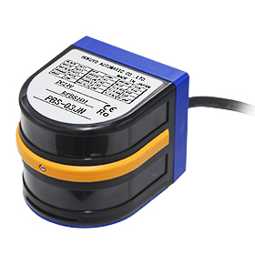
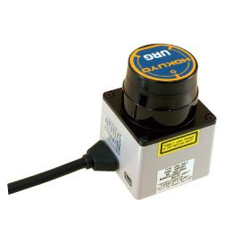
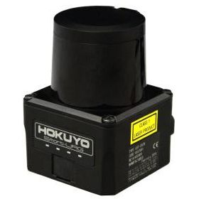
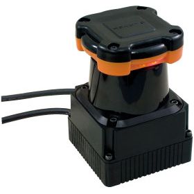
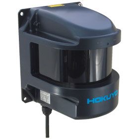
UBG-05LN
Scanning RangefinderArea Configuration
This product is no longer in production or sales.
Obstacle detection sensor with detection range (5m x 4m)
Overview
Features
-> Operation principle: A semicircular field is scanned by laser(λ=785nm). Objects present in setting area has its distance and angle measured and reported for obstacle detection.
-> Scanning angle (detection area) is 180°. Detection area is configurable from 0.1 to 5m along the length and 4m along the width. Each area has 3 detection outputs.
-> Preconfigured detection areas are switchable (up to 31 pattern) using inputs.
-> Power source is 24VDC and current consumption is 150mA or less.
System structure
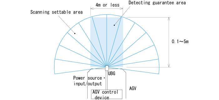
* Scanning angle 180° and step angle 0.36° with 500 steps
Specification
| Model No. | UBG-05LN |
| Power source | 24VDC(available operating range 18 to 30VDC, ripple within 10%) |
| Current consumption | 300mA on start-up, 150mA or less nominal (When 24V DC) |
| Light source | Semiconductor laser diode(λ=785nm), Laser safety class 1(FDA) |
| Detectable object | White paper with 125□ ( Reflection surface facing the sensor) |
| Detection range | Area with 0.1 to 5m(length) and 4m(width)(origin point is the scanning center) |
| Accuracy*1 | Measurement < 1m : ±20mm, measurement > 1m : 2% |
| Repeatability*1 | Measurement < 1m : ±10mm, measurement > 1m : 2% |
| Detection area setting | Output 1 : Configurable from 0 to 5m along the optical axis using 7 points. |
| Output 2, 3 : (1) Linear setting to progressive direction (2) Fan-shaped setting to optical axis | |
| direction (3) Percentage(%) setting against output 1 pointer | |
| Hysteresis | 6.25% of detecting distance |
| Output | Photo-coupler/open-collector output(30VDC 50mA or less) |
| Output 1 : OFF when detected in area | |
| Output 2 : OFF when detected in area | |
| Output 3 : OFF when detected in area | |
| Output 4(Trouble output) : ON during normal operationNote1) | |
| Output response time | 210msec or less(scanning speed 100msec/rev.)Note2) |
| Input | Photo-coupler input(Common anode, Each input ON current 4mA) |
| Detection area switching | |
| Select area No. using [Input 1], [Input 2], [Input 3], [Input 4] and [Input 5] | |
| Stop laser emission by setting [Input 1], [Input 2], [Input 3], [Input 4] and [Input 5] to ON (OFF : H level input, ON : L level input) | |
| Input response time | Input checking cycle : 1 scanning cycle (100msec) |
| (1msec when laser emission is stopped by inputs) | |
| Starting time | within 10sec from power on (It may exceed this time depending on the starting conditions) |
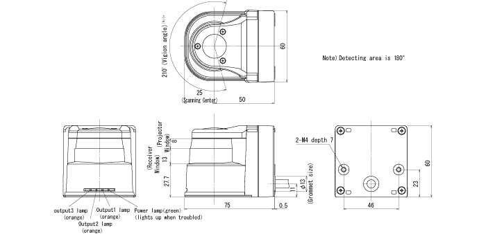
| Indicators | Power LED(Green) : Flickers when troubled or when starting |
| Output 1 LED(Orange) : Lights up when object is detected in area | |
| Output 2 LED(Orange) : Lights up when object is detected in area | |
| Output 3 LED(Orange) : Lights up when object is detected in area | |
| Connection | 1m Flying lead cable/td> |
| Ambient illuminanceNote 3) | Halogen/mercury lamp : 10,000lx or less, Fluorescent lamp : 6,000lx(Max.) |
| Ambient temperature/ humidity | -10 to +50 degrees C, 85%RH or less (No condensing, no icing) |
| Vibration resistance | 10 to 55Hz, double amplitude 1.5mm, 2 hour in each X, Y and Z directions |
| Impact resistance | 196m/s2, 10 time in each X, Y and Z directions |
| Protective structure | IP64(IEC standard) |
| Weight | 185g (260g with cable) |
| Life | 5 years (motor life) |
| Material | Front case : polycarbonate, rear case : ABS |
Note 1) Output 1 to 3 would reflect a detection state when trouble output is ON.
Note 2) It can be delayed with 1 more cycle if area switching occurs.
Note 3)Exposure to strong light such as sun light may cause malfunctioning.
Note) Hokuyo products are not developed and manufactured for use in weapons, equipment, or related technologies intended for destroying human lives or creating mass destruction. If such possibilities or usages are revealed, the sales of Hokuyo products to those customers might be halted by the laws of Japan such as Foreign Exchange Law, Foreign Trade Law or Export Trade Control Order.In addition, we will export Hokuyo products for the purpose of maintaining the global peace and security in accordance with the above laws of Japan .
External dimension
External dimension
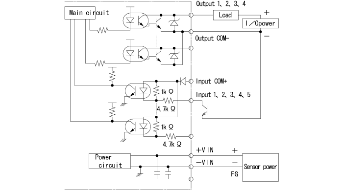
I/O Circuit
Input/output circuit
Connection
| Colors | Functions |
| Black | Output 1 |
| White | Output 2 |
| White(Blue) | Output 3 |
| Orange | Output 4(Trouble output) |
| Gray | Output common minus |
| Red | Input common plus |
| Green | Input 1 |
| Yellow | Input 2 |
| Purple | Input 3 |
| White(Yellow) | Input 4 |
| White(Purple) | Input 5 |
| Brown | +VIN(24VDC) |
| Blue | -VIN |
| Yellow(Red) | Serial input(RXD) |
| Yellow(Green) | Serial output(TXD) |
| Yellow(Black) | Serial GND |
Note 2) Connect unused input wires to input common plus(Red) or open it. Connect unused output wires to output common minus(Gray) or open it.
Note 3) Input/output direction is mentioned on the basis of UBG-05LN.
Downloads
Before Download
Only members can download the file.
If you have not registered as a member, please register as a member by clicking the "Registration".
If you are already a member, please agree to the following terms and click the "Agree".
If you have not registered as a member, please register as a member by clicking the "Registration".
If you are already a member, please agree to the following terms and click the "Agree".
License for Downloading Materials
When downloading the product specifications, drawings and various types of materials and software related to the Hokuyo's product line, please read the terms of use in advance and then utilize the same with your understanding and consent. In case of dissent, please understand that you cannot register to and be recognized in the download page. (And the Terms of Use may be revised without prior notice.)
Terms of Use
- Intellectual Property Rights
-
- Copyrights and the other rights to contents such as sentences, data and software published on this Website (hereinafter referred to as "Contents") are held by Hokuyo or its suppliers.
- The secondary application (copy, diversion, defacement, analysis, transmission, assignment, rental, licensing, and usage for the purpose of business activities or commercial gain) of the Contents on this Website posted by Hokuyo is strictly prohibited without our prior approval. Specific terms of use described for each download site or Contents shall apply in preference to the Terms of Use.
- Provision of the Contents on this Website by Hokuyo means neither a transfer of the patent rights, design rights, and/or the other intellectual property rights to inventions and designs in the Contents, nor a grant of any rights based on the intellectual property rights.
- Disclaimer
-
Hokuyo pays full attention to the information that appears on this Website, but does not take responsibility for the following items:
- The information that appears on this Website is always the latest version, and is updated or corrected timely and properly;
- The information that appears on this Website is accurate, useful and safe;
- Customer's damage incurred by the use of this Website, including changes or deletions of the information, discontinuation or suspension of the publication; and
- Any and all damage incurred by using this Website.
Download List
| Category | File name | File size | Date modified | Download |
|---|---|---|---|---|
|
|
Catalog_UBG-05LN
|
---
|
2016-03-07
|
|
|
|
Instruction Manual_UBG-05LN
|
---
|
2017-12-22
|
|
|
|
2DCAD_UBG-05LN
|
---
|
2017-04-27
|
|
|
|
3DCAD(IGES)_UBG-05LN
|
---
|
2017-04-27
|
|
|
|
3DCAD(Parasolid)_UBG-05LN
|
---
|
2017-04-27
|
|
|
|
3DCAD(STEP)_UBG-05LN
|
---
|
2017-04-27
|
|
|
|
Specifications_UBG-05LN
|
---
|
2016-03-07
|
|
|
|
Configuration Software_UBG-05LN
|
---
|
2016-03-07
|
Relation Products


Product's Category
- Scanning Rangefinder
- Photoelectric Switch
- Sensor for Iron & Steel Industry
- Optical Data Transmission Device