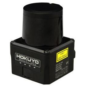
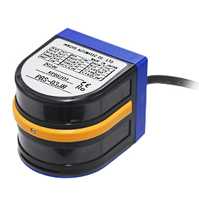
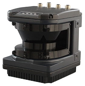
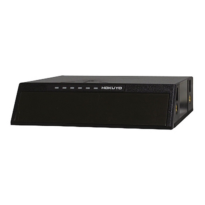
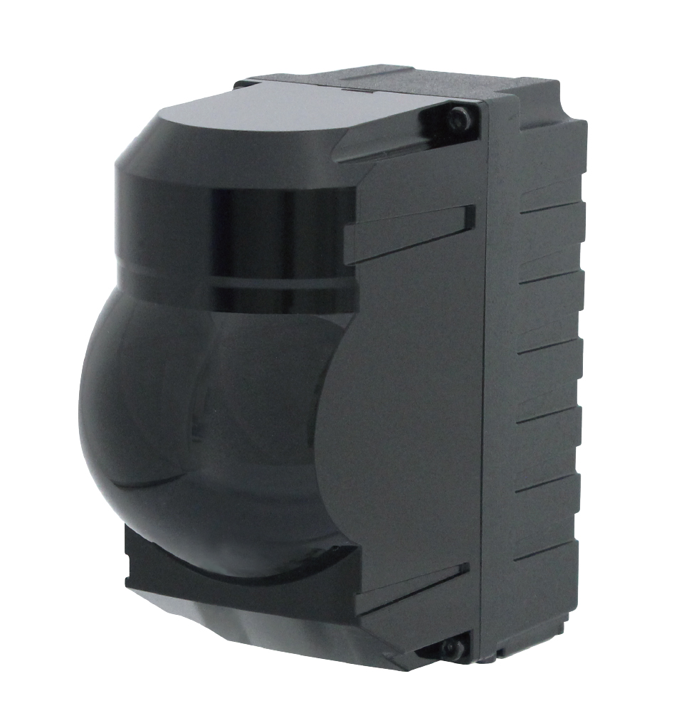
UST-05LN / UST-05LNP

Obstacle detection sensor with detection range 5m and 270° with free area settings. Compact and lightweight, it can be used to detect obstacles in AGVs (automated guided vehicles) and detect intrusions into robots, machinery, etc., NPN type: UST-05LN PNP type: UST-05LNP two types are available
Overview
Features
-> Supply voltage 10 to 30V
-> The smallest and lightest of its kind
-> Measurement distance, 5m
-> Faster response, 66msec
-> More flexible field setting available
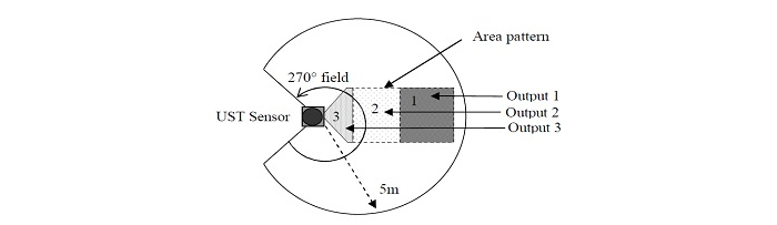
Laser scanning image
Specification
| Product name | Scanning Laser Range Finder |
| Model | UST-05LN |
| Supply voltage | DC 12V/DC 24V (operation range 10 to 30V, ripple within 10%) |
| Supply current | 150mA (DC 24V) or less (during start up about 400mA is necessary.) |
| Light source | Laser semiconductor (905nm), Laser class 1(IEC60825-1:2007, Accession number:1420210-000) |
| Detection range and object | 60mm to 5000mm (white Kent sheet) |
| 60mm to 2000mm (diffuse reflectance 10% ) | |
| Minimum detectable size 130mm (changes according to distance)*1 | |
| Accuracy | 60mm to 5000mm ±40mm*2 |
| Standard deviation | σ<20mm*2 |
| Scan angle | 270° |
| Scan speed | 25msec (motor speed 2400rpm) |
| Angular resolution | 0.5° |
| Start up time | Within 10 sec (start up time differs if malfunction is detected during start up) |
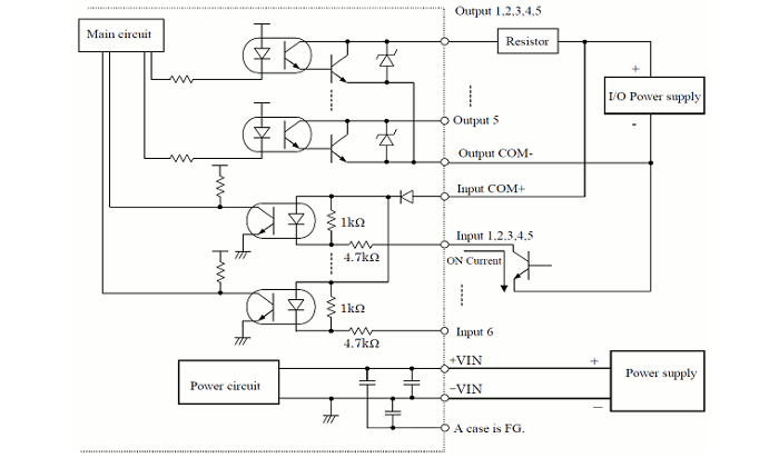
| Outputs | Photo-coupler, open collector output Max DC 30V 50mA Output 1: Output 1 OFF during object detection Output 2: Output 2 OFF during object detection Output 3: Output 3 OFF during object detection Malfunction output: ON during normal operation, OFF during malfunction Synchronization output: Synchronization signal during Master/Slave operation. Note: Output 1 to 3 are switched OFF during malfunction state |
| Inputs | Photo-coupler, common anode, power supply is 4mA when input is ON Input 1 to 5: Area switching inputs (refer Table1) Synchronization input: Input synchronization signal during Slave operation. |
| Output response time*3 | OFF : 66msec to 3241msec ON : 66msec to 3241msec |
| Hysteresis | Hysteresis 6.25% Hysteresis 3.125% No Hysteresis (Default) |
| Interface | USB |
| LED display | Blue LED: ON during normal operation,blink during the start up Output 1 LED(Orange): ON during object detection Output 2 LED(Orange): ON during object detection Output 13LED(Orange): ON during object detection |
| Synchronization function | Master/Slave Synchronization mode is set using the configuration software*4 Slave synchronization mode (0°) Slave synchronization mode (90°) Slave synchronization mode (180°) Slave synchronization mode (270°) |
| Ambient illumination | Less than 80,000lx Note : Avoid direct sunlight or other illumination sources as it may cause sensor malfunction |
| Ambient temperature and humidity | -10°C to +50°C, below 85%RH (without dew, frost) |
| Storage temperature and humidity | -30°C to +70°C, below 85%RH (without dew, frost) |
| Vibration resistance | 10 to 55Hz double amplitude of 1.5mm for 2hrs in each X, Y, and Z direction 55 to 200Hz 98m / s2 sweep of 2min for 1hr in each X,Y and Z direction |
| Shock resistance | 196m/s2 (20G) each X,Y and Z direction 10 times. |
| Insulation resistance | 10MΩ, DC 500V |
| Protective structure | IP65 |
| EMC standards | (EMI) EN61326-1:2013 EN55011:2009 + A1:2010 (EMS) EN61326-1:2013 EN61000-4-2:2009 EN61000-4-3:2006 + A1:2008 + A2:2010 EN61000-4-4:2012 EN61000-4-6:2009 EN61000-4-8:2010 |
| Weight | 130g |
| Material | Upper case: Polycarbonate, Lower case: Aluminum |
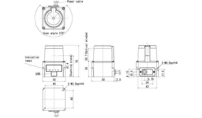
| Dimensions (W×D×H) | 50×50×70mm |
*2. Under the factory standard testing condition using white Kent sheet.
*3. Initial setting is 66msec. ON/OFF delay function switching is possible by Area Designer. Response time can be further delayed by a maximum of 1scan during the area switching.
*4. Initial setting is synchronization master. Synchronization slave setting is possible using Area Designer
External dimension
External dimension
I/O Circuit
Input/output circuit
Connection
| Color | Signal |
| Brown | +VIN(DC12V/DC24V) |
| Blue | -VIN |
| Black | Output 1 |
| White | Output 2 |
| White(Blue) | Output 3 |
| Orange | Malfunction Output |
| Light green | Synchronous Output |
| Gray | COM Output - |
| Red | COM Input + |
| Green | Input 1 |
| Yellow | Input 2 |
| Purple | Input 3 |
| White (Black) | Input 4 |
| White (Red) | Input 5 |
| Light Blue | Synchronous Input |
| Pink | Non Connect |
| Yellow(Red) | Non Connect |
| Yellow(Black) | Non Connect |
| Light Blue(Red) | Non Connect |
| Light Blue(Black) | Non Connect |
Note2 : Colors inside the bracket indicates dual color cable.
Note3 : Keep the input wires open or connect to input Com+ if not in use.
Note4 : Keep the output wires open or connect to output Com- if not in use.
Input states and corresponding area number
Area number can be switched with inputs (1 to 5) Please refer the below table.
Laser is swiched off when all inputs (1 to 5)are ON
(OFF;High level input、ON;Low level input)
Input 6: Synchronous input
| Input1 | Input2 | Input3 | Input4 | Input5 | Area Number |
| ON | ON | ON | ON | ON | Laser off*1 |
| OFF | ON | ON | ON | ON | Area1 |
| ON | OFF | ON | ON | ON | Area2 |
| OFF | OFF | ON | ON | ON | Area3 |
| ON | ON | OFF | ON | ON | Area4 |
| OFF | ON | OFF | ON | ON | Area5 |
| ON | OFF | OFF | ON | ON | Area6 |
| OFF | OFF | OFF | ON | ON | Area7 |
| ON | ON | ON | OFF | ON | Area8 |
| OFF | ON | ON | OFF | ON | Area9 |
| ON | OFF | ON | OFF | ON | Area10 |
| OFF | OFF | ON | OFF | ON | Area11 |
| ON | ON | OFF | OFF | ON | Area12 |
| OFF | ON | OFF | OFF | ON | Area13 |
| ON | OFF | OFF | OFF | ON | Area14 |
| OFF | OFF | OFF | OFF | ON | Area15 |
| ON | ON | ON | ON | OFF | Area16 |
| OFF | ON | ON | ON | OFF | Area17 |
| ON | OFF | ON | ON | OFF | Area18 |
| OFF | OFF | ON | ON | OFF | Area19 |
| ON | ON | OFF | ON | OFF | Area20 |
| OFF | ON | OFF | ON | OFF | Area21 |
| ON | OFF | OFF | ON | OFF | Area22 |
| OFF | OFF | OFF | ON | OFF | Area23 |
| ON | ON | ON | OFF | OFF | Area24 |
| OFF | ON | ON | OFF | OFF | Area25 |
| ON | OFF | ON | OFF | OFF | Area26 |
| OFF | OFF | ON | OFF | OFF | Area27 |
| ON | ON | OFF | OFF | OFF | Area28 |
| OFF | ON | OFF | OFF | OFF | Area29 |
| ON | OFF | OFF | OFF | OFF | Area30 |
| OFF | OFF | OFF | OFF | OFF | Area31 |
Downloads
Before Download
If you have not registered as a member, please register as a member by clicking the "Registration".
If you are already a member, please agree to the following terms and click the "Agree".
License for Downloading Materials
When downloading the product specifications, drawings and various types of materials and software related to the Hokuyo's product line, please read the terms of use in advance and then utilize the same with your understanding and consent. In case of dissent, please understand that you cannot register to and be recognized in the download page. (And the Terms of Use may be revised without prior notice.)
Terms of Use
- Intellectual Property Rights
-
- Copyrights and the other rights to contents such as sentences, data and software published on this Website (hereinafter referred to as "Contents") are held by Hokuyo or its suppliers.
- The secondary application (copy, diversion, defacement, analysis, transmission, assignment, rental, licensing, and usage for the purpose of business activities or commercial gain) of the Contents on this Website posted by Hokuyo is strictly prohibited without our prior approval. Specific terms of use described for each download site or Contents shall apply in preference to the Terms of Use.
- Provision of the Contents on this Website by Hokuyo means neither a transfer of the patent rights, design rights, and/or the other intellectual property rights to inventions and designs in the Contents, nor a grant of any rights based on the intellectual property rights.
- Disclaimer
-
Hokuyo pays full attention to the information that appears on this Website, but does not take responsibility for the following items:
- The information that appears on this Website is always the latest version, and is updated or corrected timely and properly;
- The information that appears on this Website is accurate, useful and safe;
- Customer's damage incurred by the use of this Website, including changes or deletions of the information, discontinuation or suspension of the publication; and
- Any and all damage incurred by using this Website.
Download List
| Category | File name | File size | Date modified | Download |
|---|---|---|---|---|
|
|
Catalog_UST-05LN
|
---
|
2025-07-04
|
|
|
|
Catalog_UST-05LNP
|
---
|
2025-07-04
|
|
|
|
Specifications_UST-05LN
|
---
|
2025-03-06
|
|
|
|
Specifications_UST-05LNP
|
---
|
2025-03-06
|
|
|
|
Users Manual_UST-05LN/05LA series
|
---
|
2025-10-01
|
|
|
|
Users Manual _UST-05LNP/05LAP series
|
---
|
2025-10-01
|
|
|
|
AreaDesigner_3.4.1(R.3335_C.462)_installer.exe
|
---
|
2026-03-17
|
|
|
|
2DCAD_UST-05LN
|
---
|
2017-04-27
|
|
|
|
3DCAD(IGES)_UST-05LN
|
---
|
2017-04-27
|
|
|
|
3DCAD(STEP)_UST-05LN
|
---
|
2017-04-27
|
|
|
|
Instruction Manual_Area Designer(Configuration software)
|
---
|
2025-10-01
|
|
|
|
USB Driver(Win)
|
---
|
2019-07-19
|
Relation Products


- Scanning Rangefinder
- Photoelectric Switch
- Sensor for Iron & Steel Industry
- Optical Data Transmission Device