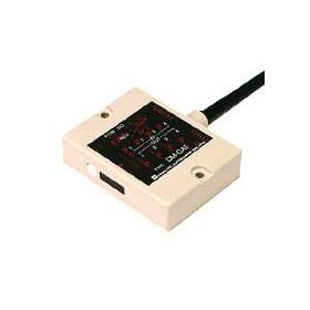
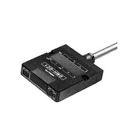
DMJ-G/HB1

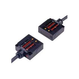
This is Parallel I/O (8-bit) with RJ-11 modular cable type.
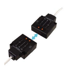
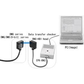
It communicates wirelessly (infrared ray) between mobile vehicles sides such as AGVs (Automated Guided Vehicles) and the station sides by using this.
This is provided with a logging function and corresponded to SEMI E84.
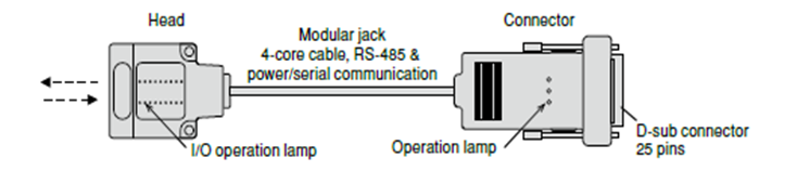
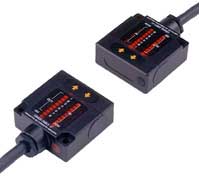
This composes of Head, Connector and RJ-11 cable, it is user friendly to make wiring.
Overview
Features
->Modular cable is applied between a head and a connector of E84 parallel I/O and it is easy to make a wiring
->This device has logging function (up to 100 times data changes)
Model
●Sensor head
| Model No. | Part No. | Direction | Transmission distance |
| DMJ-GB1 | WDMJ003 | Head-ON | 1m |
| DMJ-HB1 | WDMJ004 | Side-ON |
●Connector
| Model No. | Part No. | Mode | Fixed screw |
| DMJ-CN1 | WDMJ005 | Changeover of transmission/reception standby mode by outer input | Metric screw (M2.6) |
| DMJ-CN2 | WDMJ006 | Changeover of transmission/reception standby mode by outer input | Inch screw (#4-40UNC) |
| DMJ-CN3 | WDMJ007 | Reception standby mode (Fixed) | Metric screw (M2.6) |
| DMJ-CN4 | WDMJ008 | Reception standby mode (Fixed) | Inch screw (#4-40UNC) |
SEMI E84 compatible products list *1
| Model No. | Part No. | Direction | Cable length | SEMI E84 standard/ D-sub 25pin connector *3 |
Mode *2 | Logging data *4 | Remarks |
| DMJ-GB1 (Sensor) |
WDMJ003 | Head-ON | - | - | - | 100 times | - |
| DMJ-HB1 (Sensor) |
WDMJ004 | Side-ON | - | - | - | 100 times | - |
| DMJ-CN1 (Connector) |
WDMJ005 | - | - | Provided (Metric screw) |
Changeover of transmission/ reception standby |
- | - |
| DMJ-CN2 (Connector) |
WDMJ006 | - | - | Provided (Inch screw) |
Changeover of transmission/ reception standby |
- | - |
| DMJ-CN3 (Connector) |
WDMJ007 | - | - | Provided (Metric screw) |
Reception standby | - | - |
| DMJ-CN4 (Connector) |
WDMJ008 | - | - | Provided (Inch screw) |
Reception standby | - | - |
| DMJ-GB1-Z01 (Sensor) |
WDMJ010 | Head-ON | - | - | - | 100 times | High-frequency noise resistance |
| DMJ-HB1-Z01 (Sensor) |
WDMJ011 | Side-ON | - | - | - | 100 times | High-frequency noise resistance |
| DMJ-CN3-Z01 (Connector) |
WDMJ013 | - | - | Provided (Metric screw) |
Reception standby | - | High-frequency noise resistance |
| DMJ-CN4-Z01 (Connector) |
WDMJ014 | - | - | Provided (Inch screw) |
Reception standby | - | High-frequency noise resistance |
| DMJ-HB1-Z50 (Sensor) |
WDMJ015 | Side-ON | - | - | - | 1600 times | Ambient light resistance |
| DMJ-GB1-Z50 (Sensor) |
WDMJ020 | Head-ON | - | - | - | 1600 times | Ambient light resistance |
| DMJ-CN3-Z50 (Connector) |
WDMJ016 | - | - | Provided (Metric screw) |
Reception standby | - | Ambient light resistance |
| DMJ-CN4-Z50 (Connector) |
WDMJ017 | - | - | Provided (Inch screw) |
Reception standby | - | Ambient light resistance |
| Modular cable (White) | WZ00067 | - | 5m | - | - | - | RJ-11 connector at both ends |
| Modular cable (Black) | WZ00068 | - | 5m | - | - | - | RJ-11 connector at both ends |
*2 It may be necessary to notify the model to be adopted in advance.
*3 The pin assignment is compliant with SEMI E84. There are two types of fixing screws, metric screws and inch screws. Devices that support SEMI E84-0699, -0999 may use metric screws. Inch screws are specified for SEMI E84-0200A and later versions.
*4 Recommended product. The logging function is effective in investigating the cause when a transfer problem occurs. Since the log data can be easily sent by attaching it to an e-mail, it is possible to immediately analyze the defect phenomenon in-house even in the case of troubles with overseas users.
Specification
Sensor head
| Model No. | DMJ-GB1(WDMJ003) | DMJ-HB1(WDMJ004) | |||
| Direction | HEAD-ON | SIDE-ON |
Connector
| Model No. | DMJ-CN1 (WDMJ005) |
DMJ-CN2 (WDMJ006) |
DMJ-CN3 (WDMJ007) |
DMJ-CN4 (WDMJ008) |
|
| Transmission method | Changeover of transmission/reception standby mode by outer input | Changeover of transmission/reception standby mode by outer input | Reception standby mode(Fixed) | Reception standby mode(Fixed) | |
| Fixed screw | Metric screw (M2.6) | Inch screw (#4-40UNC) |
Metric screw (M2.6) | Inch screw (#4-40UNC) |
|
| Power source | DC24V | ||||
| Current consumption | 100mA Max. | ||||
| Transmission distance | 1.0m (can be adjusted by adjuster) | ||||
| Directional angle | 30 degree (Full angle) | ||||
| Transmission capacity(I/O) | 8-bit/8-bit | ||||
| Transmission method | Half-duplex two-way transmission | ||||
| Transmission time | 45ms | ||||
| Modulating system | Pulse modulation | ||||
| Detecting system | Parity check, All output is getting OFF when twice continuous error | ||||
| Specifications between a head and a connector | Communicating standard | RS-485 | |||
| Communicating speed | 38.4kbps | ||||
| Detecting system | Parity check/SUM check | ||||
| Connection | RJ-11(Modular jack) Max.extending length 200m | ||||
| Logging data | Data variable time | Max.100 times *1 | |||
| Memorizing data | Transmitting/Receiving data: Each 8bits, GO output, SELECT input | ||||
| Measuring unit of invariable time | 0.05s | ||||
| Measuring error of invariable time | ±0.05s | ||||
| Measuring range of invariable time | Max.1638.35s (Approx.27min.) *2 | ||||
| Memorizing media | Ferroelectric memory (512 bytes) | ||||
| Memorizing cycle | Min.20msec | ||||
| Memorizing life | Nos.1010times, 10 years | ||||
| Operating lamps | Head | Each parallel I/O is shown. I/O is the same indication as standard device(8-bit type) IN: 8 points, OUT: 8 points, GO, POW, NS NS: Lights up when serial communication with connector is normal. |
|||
| Connector | NS:Lights up when serial communication with head is normal. MODE:Lights up when reception-standby mode POW:Lights up when putting power source in |
||||
| Ambient illuminance | 4,000lx or less | ||||
| Ambient temprature/humidity | -10 to 50 degC / 85%RH or less (Not freezing) | ||||
| Vibration resistance | Double amplitude 1.5mm, 10 to 55 Hz, Each 2 hour in X,Y and Z directions | ||||
| Impact resistance | 500m/s2 Each 10 time in X,Y and Z directions | ||||
| Connection | D-sub 25 pins connector | ||||
| Protective structure | IP40 | ||||
| Case | Polycarbonate | ||||
| Weight | Head:Approx.50g, Connector:Approx.70g | ||||
*2 In case that measuring of invariable data for transmitting/receiving data exceeds max. value, it is memorized as max. value.
Connection cable WZ00033 (cable length 5 m) is available as an option.
Special products (DMJ-G / H-Z series) compatible with SEMI E84 are listed on the model line-up page.
External dimension
Head
.PNG)
Connector
.PNG)
I/O Circuit
Input section (common)
DMJ.PNG)
*Don't use 2-wire sensor. Operating threshold current 1.5~2mA.
Output section (common)
DMJ.PNG)
Connection
| Pin No. | Functions | Specifications | Pin No. | Functions | Specifications |
| 1 | IN1 | Input data | 14 | OUT1 | Output data |
| 2 | IN2 | 15 | OUT2 | ||
| 3 | IN3 | 16 | OUT3 | ||
| 4 | IN4 | 17 | OUT4 | ||
| 5 | IN5 | 18 | OUT5 | ||
| 6 | IN6 | 19 | OUT6 | ||
| 7 | IN7 | 20 | OUT7 | ||
| 8 | IN8 | 21 | OUT8 | ||
| 9 | NC. | ― | 22*1 | +VIN | Power (24VDC±10%) |
| 10 | SELECT | When shorted to COM(No.25) : Stop to communicate When opened : Communication is available |
23*1 | +VIN | |
| 11 | MODE*3 | When shorted to COM (No.25) : Reception standby mode When opened : Transmittion standby mode |
24*2 | -VIN | Power (0V) |
| 12 | GO | ON : Normal data reception OFF : Interrupting the light |
25*2 | COM | COM Common for I/O |
| 13 | NC. | ― |
*2 It is short-circuited between -VIN(No.24) and COM (No.25) inside.
*3 MODE is available only for DMJ-CN1 and DMJ-CN2.
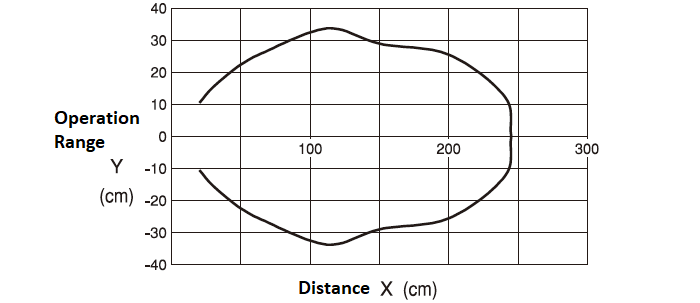
Characteristics Data
Characteristics (Example, in case of combination with the DMS series)
Downloads
Before Download
If you have not registered as a member, please register as a member by clicking the "Registration".
If you are already a member, please agree to the following terms and click the "Agree".
License for Downloading Materials
When downloading the product specifications, drawings and various types of materials and software related to the Hokuyo's product line, please read the terms of use in advance and then utilize the same with your understanding and consent. In case of dissent, please understand that you cannot register to and be recognized in the download page. (And the Terms of Use may be revised without prior notice.)
Terms of Use
- Intellectual Property Rights
-
- Copyrights and the other rights to contents such as sentences, data and software published on this Website (hereinafter referred to as "Contents") are held by Hokuyo or its suppliers.
- The secondary application (copy, diversion, defacement, analysis, transmission, assignment, rental, licensing, and usage for the purpose of business activities or commercial gain) of the Contents on this Website posted by Hokuyo is strictly prohibited without our prior approval. Specific terms of use described for each download site or Contents shall apply in preference to the Terms of Use.
- Provision of the Contents on this Website by Hokuyo means neither a transfer of the patent rights, design rights, and/or the other intellectual property rights to inventions and designs in the Contents, nor a grant of any rights based on the intellectual property rights.
- Disclaimer
-
Hokuyo pays full attention to the information that appears on this Website, but does not take responsibility for the following items:
- The information that appears on this Website is always the latest version, and is updated or corrected timely and properly;
- The information that appears on this Website is accurate, useful and safe;
- Customer's damage incurred by the use of this Website, including changes or deletions of the information, discontinuation or suspension of the publication; and
- Any and all damage incurred by using this Website.
Download List
| Category | File name | File size | Date modified | Download |
|---|---|---|---|---|
|
|
Catalog_DMJ Please check the Catalog Correction Notice included in the ZIP file as well.
|
---
|
2026-06-09
|
|
|
|
Specifications_DMJ-GHB1
|
---
|
2025-10-01
|
|
|
|
Specification_DMJ-GHB1-Z01
|
---
|
2022-05-24
|
|
|
|
Specifications_DMJ-GHB1-Z50
|
---
|
2025-10-01
|
|
|
|
2D CAD_DMJ-GHB1
|
---
|
2022-06-16
|
|
|
|
2DCAD_DMJ-CN
|
---
|
2022-05-26
|
|
|
|
3DCAD_DMJ-GHB1
|
---
|
2022-05-24
|
|
|
|
3DCAD_DMJ-CN
|
---
|
2022-05-24
|
Relation Products


- Scanning Rangefinder
- Photoelectric Switch
- Sensor for Iron & Steel Industry
- Optical Data Transmission Device