DMS-G/H-E


High-frequency noise resistance type of DMS series.
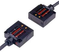
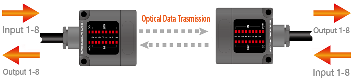
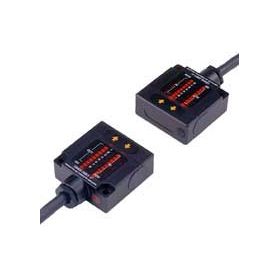
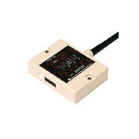
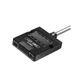
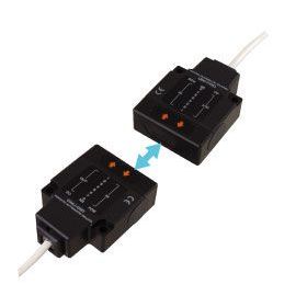
The Optical Data Transmission Device to meet the needs of compactness and lightness.
Body size 50x50x20mm is only half of our previous model DM series.
Weight 210g is much lighter than before.
Overview
Features
*This is high-frequency noise resistance type of DMS series.
*NPN and PNP type are lined up.
*This is compatible with SEMI E84.
Easy friendly to control with parallel signals
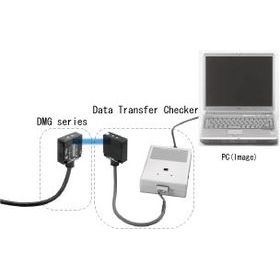
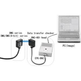
Communicable with wireless between AGVs and Stations

High-Frequency Noise Resistance
This device can also communicate with the original DMS and DMG series.
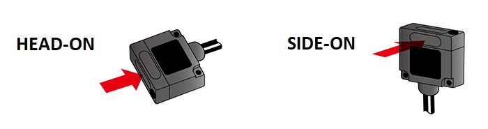
2 types of optical axis direction selectable based on the installation way
Model
| Model number | Code number | Directional mounting | Transmission distance | Signals |
| DMS-GA1-E | WDMS214 | Head-on | 1m* | 4-bit |
| DMS-GB1-E | WDMS191 | 8-bit | ||
| DMS-GB2-E | WDMS195 | 3m* | ||
| DMS-GB1-E70 | WDMS193 | 1m* | ||
| DMS-GB2-E70 | WDMS197 | 3m* | ||
| DMS-HA1-E | WDMS205 | Side-on | 1m* | 4-bit |
| DMS-HB1-E | WDMS192 | 8-bit | ||
| DMS-HB2-E | WDMS196 | 3m* | ||
| DMS-HB1-E70 | WDMS194 | 1m* | ||
| DMS-HB2-E70 | WDMS198 | 3m* |
Specification
| Type | NPN Output type | |||||
| 4-bit type | 8-bit type | |||||
| Model No. | DMS-GA1-E | DMS-HA1-E | DMS-GB1-E | DMS-HB1-E | DMS-GB2-E | DMS-HB2-E |
| Directional mounting | Head-on | Side-on | Head-on | Side-on | Head-on | Side-on |
| Transmision distance | 1.0m* | 1.0m* | 3.0m* | |||
| Directional angle (Full angle) |
20° | 20° | 10° | |||
| Transmission method | Half-duplex two-way transmission | |||||
| Transmission time | 40ms | |||||
| Modulation method | Pulse modulation | |||||
| Detection method | Parity check | |||||
| Power source | 24VDC(10~30V) | |||||
| Current consumption | 100mA Max. | |||||
| Ambient illuminance | 4,000lx or less | |||||
| Ambient temperature/humidity | -10~50℃・85RH or less | |||||
| Vibration resistance | Double amplitude 1.5mm 10~55 Hz, each 2 hours in X,Y and Z directions | |||||
| Impact resistance | 500m/s2 each 10 times in X,Y and Z directions | |||||
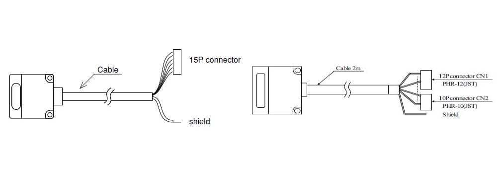
| Connection | Flying lead cable (0.2mm2 15-core shield wire) |
Flying lead cable(0.2mm2 22-core shield wire) | ||||
| Protective structure | IP64 (not included the connector) | |||||
| Input | Contact or non-contact open-collector input (ON current 2.5mA or more, OFF current 1mA or less, Operation threshold current 1.5~2mA) |
|||||
| Output | NPN open collector-output(30VDC・50mA、Residucal voltage 1.8V or less) | |||||
Notes
| Type | PNP Output type | |||
| 8-bit type | ||||
| Model No. | DMS-GB1-E70 | DMS-HB1-E70 | DMS-GB2-E70 | DMS-HB2-E70 |
| Directional mounting | Head-on | Side-on | Head-on | Side-on |
| Transmision distance | 1.0m* | 3.0m* | ||
| Directional angle(Full angle) | 20° | 10° | ||
| Transmission method | Half-duplex two-way transmission | |||
| Transmission time | 40ms | |||
| Modulation method | Pulse modulation | |||
| Detection method | Parity check | |||
| Power source | 24VDC(10~30V) | |||
| Current consumption | 100mA Max. | |||
| Ambient illuminance | 4,000lx or less | |||
| Ambient temperature/humidity |
-10~50℃・85RH or less | |||
| Vibration resistance | Double amplitude 1.5mm 10~55 Hz, each 2 hours in X,Y and Z directions | |||
| Impact resistance | 500m/s2 each 10 times in X,Y and Z directions | |||
| Connection | Flying lead cable(0.2mm2 22-core shield wire) | |||
| Protective structure | IP64 (not included the connector) | |||
| Input | Contact or non-contact open-collector input(LOW: 0~6V HIGH: 11~30V) | |||
| Output | PNP open-collector output(Output current MAX. 50mA) | |||
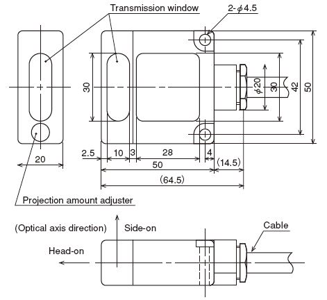
External dimension
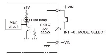
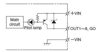
I/O Circuit
Connection (NPN type) (Drawing is 4-bit type on the left, 8-bit type on the right)
| 4BIT type | 8BIT type | ||
| Item | Size | Item | Size |
| Conductor size | 25AWG | Conductor size | 25AWG |
| Conductor outer diameter | 0.54mm | Conductor outer diameter | 0.54mm |
| Wire core outer diameter | 1.04mm | Wire core outer diameter | 1.04mm |
| Finished outer diameter | 7.0mm | Finished outer diameter | 8.2mm |
■Pin No.
4 BIT type
| Colors | Pin No. | Functions |
| Black | 1 | IN1 |
| Brown | 2 | IN2 |
| Red | 3 | IN3 |
| Orange | 4 | IN4 |
| White/Yellow | 5 | MODE |
| Yellow | 6 | SELECT |
| White/Blue | 7 | NC |
| Green | 8 | OUT1 |
| Blue | 9 | OUT2 |
| Purple | 10 | OUT3 |
| Gray | 11 | OUT4 |
| White | 12 | GO |
| Yellow/Green | 13 | COM (0V) |
| Yellow/Red | 14 | +VIN |
| Yellow/ Black | 15 | -VIN (0V) |
| Shield | Shield | |
8 BIT type
| Connector(1) | Connector(2) | ||||
| Colors | Pin No. | Functions | Colors | Pin No. | Functions |
| Light blue | 1 | COM | Green | 1 | IN5 |
| Pink | 2 | MODE*1 | Green/Black | 2 | OUT5 |
| White | 3 | SELECT*2 | Blue | 3 | IN6 |
| White/Black | 4 | GO*3 | Blue/Black | 4 | OUT6 |
| Brown | 5 | IN1 | Purple | 5 | IN7 |
| Brown/Black | 6 | OUT1 | Purple/Black | 6 | OUT7 |
| Red | 7 | IN2 | Gray | 7 | IN8 |
| Red/Black | 8 | OUT2 | Gray/Black | 8 | OUT8 |
| Orange | 9 | IN3 | Pink/Black | 9 | +VIN |
| Orange/Black | 10 | OUT3 | Light blue/Black | 10 | -VIN |
| Yellow | 11 | IN4 | Shield | Shield | |
| Yellow/Black | 12 | OUT4 | |||
●Transmission standby mode when it is opened between MODE and I/O COM.
●Reception standby mode when it is short circuited between MODE and I/O COM.
*2 Select input
This is designed to arbitarily stop transmission and reception operation by outside signal.
●Operated when it is opened between SELECT and I/O COM.
●Stops operation when it is short circuited between SELECT and I/O COM.
*3 GO output
This is designed to check for correct reception of optical signal.
●It is ON when optical signal is receiving.
●It is OFF when optical signal is interrupted (or non-receiving state).
Note) Terminal ends handling of not using Input, Output, SELECT input, MODE input are to be treated individually and not connecting to the other cables. If handled in one treatment, it will cause malfunction.
Note) The connector attached on the end of cable can not be used as connecting terminal.
Note) COM and -VIN are shorted internally.
Input section (NPN)
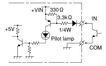
Operation threshold current: 1.5~2mA
Output section (NPN)
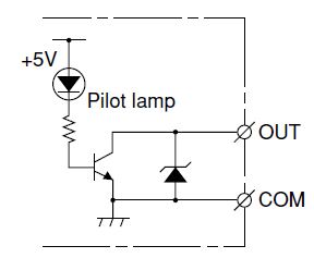
30VDC 50mA or less
Residual voltage 1.8V or less
Connection (PNP type : 8-bit type only available)
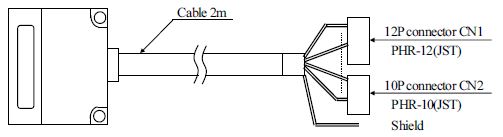
| 8BIT type | |
| Item | Size |
| Conductor size | 25AWG |
| Conductor outer diameter | 0.54mm |
| Wire core outer diameter | 1.04mm |
| Finished outer diameter | 8.2mm |
■Pin No.
| Connector(1) | Connector(2) | ||||
| Colors | Pin No. | Functions | Colors | Pin No. | Functions |
| Light blue/Black | 1 | -VIN | Pink | 1 | MODE*1 |
| Pink/Black | 2 | +VIN | White/Black | 2 | GO*3 |
| Brown | 3 | IN1 | Gray/Black | 3 | OUT8 |
| Red | 4 | IN2 | Purple/Black | 4 | OUT7 |
| Orange | 5 | IN3 | Blue/Black | 5 | OUT6 |
| Yellow | 6 | IN4 | Green/Black | 6 | OUT5 |
| Green | 7 | IN5 | Yellow/Black | 7 | OUT4 |
| Blue | 8 | IN6 | Orange/Black | 8 | OUT3 |
| Purple | 9 | IN7 | Red/Black | 9 | OUT2 |
| Gray | 10 | IN8 | Brown/Black | 10 | OUT1 |
| White | 11 | SELECT*2 | Shield | Shield | |
| Light blue | 12 | COM | |||
●Transmission standby mode when it is opened between MODE and I/O +VIN.
●Reception standby mode when it is short circuited between MODE and I/O +VIN.
*2 Select input
This is designed to arbitrarily stop transmission and reception operation by outside signal.
●Operated when it is opened between SELECT and I/O +VIN.
●Stops operation when it is short circuited between SELECT and I/O +VIN.
*3 GO output
This is designed to check for correct reception of optical signal.
●It is ON when optical signal is receiving.
●It is OFF when optical signal is interrupted (or non-receiving state).
Note) Terminal ends handling of not using Input, Output, SELECT input, MODE input are to be treated individually and not connecting to the other cables. If handled in one treatment, it will cause malfunction.
Note) The connector attached on the end of cable cannot be used as connecting terminal.
Note) COM and -VIN are shorted internally.
Input section (PNP)
HIGH: 11~30V
Output section (PNP)
Max. 30VDC 50mA
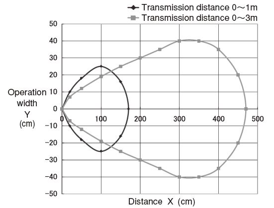
Characteristics Data
Transmission area
Downloads
Before Download
If you have not registered as a member, please register as a member by clicking the "Registration".
If you are already a member, please agree to the following terms and click the "Agree".
License for Downloading Materials
When downloading the product specifications, drawings and various types of materials and software related to the Hokuyo's product line, please read the terms of use in advance and then utilize the same with your understanding and consent. In case of dissent, please understand that you cannot register to and be recognized in the download page. (And the Terms of Use may be revised without prior notice.)
Terms of Use
- Intellectual Property Rights
-
- Copyrights and the other rights to contents such as sentences, data and software published on this Website (hereinafter referred to as "Contents") are held by Hokuyo or its suppliers.
- The secondary application (copy, diversion, defacement, analysis, transmission, assignment, rental, licensing, and usage for the purpose of business activities or commercial gain) of the Contents on this Website posted by Hokuyo is strictly prohibited without our prior approval. Specific terms of use described for each download site or Contents shall apply in preference to the Terms of Use.
- Provision of the Contents on this Website by Hokuyo means neither a transfer of the patent rights, design rights, and/or the other intellectual property rights to inventions and designs in the Contents, nor a grant of any rights based on the intellectual property rights.
- Disclaimer
-
Hokuyo pays full attention to the information that appears on this Website, but does not take responsibility for the following items:
- The information that appears on this Website is always the latest version, and is updated or corrected timely and properly;
- The information that appears on this Website is accurate, useful and safe;
- Customer's damage incurred by the use of this Website, including changes or deletions of the information, discontinuation or suspension of the publication; and
- Any and all damage incurred by using this Website.
Download List
| Category | File name | File size | Date modified | Download |
|---|---|---|---|---|
|
|
Specifications_DMS-GB1/HB1/GB2/GB2-E
|
---
|
2025-06-09
|
|
|
|
Specifications_DMS-GB1/HB1/GB2/HB2-E70
|
---
|
2025-06-09
|
|
|
|
Instruction Manual_DMS-H/GA1-E
|
---
|
2022-06-08
|
|
|
|
Instruction Manual_DMS-H/GB1/2-E
|
---
|
2022-07-12
|
|
|
|
Instruction Manual_DMS-H/GB1/2-E70
|
---
|
2022-06-08
|
|
|
|
2DCAD_DMS_DMG
|
---
|
2022-08-18
|
|
|
|
3DCAD(IGES)_DMS_DMG
|
---
|
2025-10-01
|
|
|
|
3DCAD(Parasolid)_DMS_DMG
|
---
|
2025-10-01
|
|
|
|
3DCAD(STEP)_DMS_DMG
|
---
|
2025-10-01
|
|
|
|
Catalog_DMS-E_E70
|
---
|
2026-06-09
|
Relation Products
- Scanning Rangefinder
- Photoelectric Switch
- Sensor for Iron & Steel Industry
- Optical Data Transmission Device